
GEAR COUPLING
Gear couplings are torsionally rigid and are equipped to two styles â completely adaptable and versatile/rigid. A totally adaptable coupling includes two hubs with an exterior equipment and two outer sleeves with an inside gear. It really is a universal coupling for all sorts of apps and accommodates all attainable misalignments (angular, offset and combined) as effectively as massive axial times. Machines, bearings, seals, and shafts are consequently not subjected to the added forces, occasionally of significant magnitude, which occur from unavoidable misalignment normally connected with rigid shaft couplings.
A adaptable/rigid coupling includes one particular adaptable geared 50 % and one rigid fifty percent. It does not accommodate parallel displacement of shafts but does accommodate angular misalignment. This sort of couplings are largely utilised for “floating shaft” applications.
Measurements 010 â 070 all have crowned teeth with a 20° pressure make contact with (fig one). This enables to accommodate up to 1,5° static angular misalignment per equipment mesh. Nonetheless, reducing the operational misalignment will optimize the 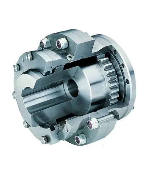 existence of the coupling as nicely as the existence of other equipment components this sort of as bearings and so forth.
Gear COUPLING
gear coupling is a torsionally rigid grease crammed coupling consisting of two hubs with exterior multicrown – and two flanged sleeves with straight internal teeth. The flanged sleeves are bolted together with large energy corrosion safeguarded equipped bolts and nuts. The sleeve is at the reverse aspect of the flange executed with an endcap (inside for tiny and screwed for big measurement couplings) in which the o-ring is positioned for sealing needs. The equipment coupling has been created to transmit the torque among these two flanges through friction steering clear of fretting corrosion between these faces.
The enamel of hub and sleeve are continually in make contact with with each and every other and have been created with the essential backlash to accommodate angular-, parallel- and axial misalignment inside of their misalignment ability. The angular and parallel misalignment capacity is decided by the equipment tooth layout and is for the normal equipment max. one.5° degrees (two x .75°) in total. The axial misalignment capacity is minimal by the equipment enamel duration in the sleeve and can be different (optionally).
Want daily news letters concerning CHINA GEAR COUPLING? Please go to the site.