Product Description
1.Product Description
Gear shaft, Herringbone Gear Shaft, Bevel Gear, Eccentric Shaft mainly used on vessel engine, fan internal gear
1.1. Bevel Gear, Pinion Shaft Processing
Gear drawing— Simulation Modelling—Making casting model—Casting— Primary Detection—Rough machining—Hardening Tempering—Semi-finishing machining —Hobbing—Tooth Surface Quenching—Gear grinding—Gear Surface Carburzing—Inspection—Spray Anti-rust Oil—Package—Delivery
Gear Shaft drawing CHECK, Make Forging Mold, Forging Mold Quality Inspection Check, Machine Processing, Check Size\Hardness\Surface Finish and other technical parameters on drawing.
2.2. Bevel Gear Package
Spray anti-rust oil on Herringbone Gear Shaft, Wrap waterproof cloth around Gear Shaft for reducer, Prepare package by shaft shape&weight to choose steel frame, steel support or wooden box etc.
1.3. OEM Customized Pinion Shaft
We supply OEM SERVICE, customized herringbone gear shaft with big module, more than 1tons big weight, more than 3m length, 42CrMo/35CrMo or your specified required material gear shaft.
2.Product Technical info.
| Module | m | Range: 5~70 |
| Gear Teeth Number | z | OEM by drawing’s technical parameters |
| Teeth Height | H | OEM by drawing’s technical parameters |
| Teeth Thickness | S | OEM by drawing’s technical parameters |
| Tooth pitch | P | OEM by drawing’s technical parameters |
| Tooth addendum | Ha | OEM by drawing’s technical parameters |
| Tooth dedendum | Hf | OEM by drawing’s technical parameters |
| Working height | h’ | OEM by drawing’s technical parameters |
| Bottom clearance | C | OEM by drawing’s technical parameters |
| Pressure Angle | α | OEM by drawing’s technical parameters |
| Helix Angle, | OEM by drawing’s technical parameters | |
| Surface hardness | HRC | Range: HRC 50~HRC63(Quenching) |
| Hardness: | HB | Range: HB150~HB280; Hardening Tempering/ Hardened Tooth Surface |
| Surface finish | Range: Ra1.6~Ra3.2 | |
| Tooth surface roughness | Ra | Range: ≥0.4 |
| Gear Accuracy Grade | Grade Range: 5-6-7-8-9 (ISO 1328) | |
| Diameter | D | Range: 1m~16m |
| Weight | Kg | Range: Min. 100kg~Max. 80tons Single Piece |
| Gear Position | Internal/External Gear | |
| Toothed Portion Shape | Spur Gear/Bevel/Spiral/Helical/Straight | |
| Shaft shape | Herringbone Gear Shaft / Gear Shaft / Eccentric Shaft / Spur Gear / Girth Gear / Gear Wheel | |
| Material | Forging/ Casting |
Forging/ Casting 45/42CrMo/40Cr or OEM |
| Manufacturing Method | Cut Gear | |
| Gear Teeth Milling | √ | |
| Gear Teeth Grinding | √ | |
| Heat Treatment | Quenching /Carburizing | |
| Sand Blasting | Null | |
| Testing | UT\MT | |
| Trademark | TOTEM/OEM | |
| Application | Gearbox, Reducer, Petroleum,Cement,Mining,Metallurgy etc. Wind driven generator,vertical mill reducer,oil rig helical gear,petroleum slurry pump gear shaft |
|
| Transport Package | Export package (wooden box, steel frame etc.) | |
| Origin | China | |
| HS Code | 8483409000 |
Material Comparison List
| STEEL CODE GRADES COMPARISON | |||||
| CHINA/GB | ISO | ГΟСТ | ASTM | JIS | DIN |
| 45 | C45E4 | 45 | 1045 | S45C | CK45 |
| 40Cr | 41Cr4 | 40X | 5140 | SCr440 | 41Cr4 |
| 20CrMo | 18CrMo4 | 20ХМ | 4118 | SCM22 | 25CrMo4 |
| 42CrMo | 42CrMo4 | 38XM | 4140 | SCM440 | 42CrMo4 |
| 20CrMnTi | 18XГT | SMK22 | |||
| 20Cr2Ni4 | 20X2H4A | ||||
| 20CrNiMo | 20CrNiMo2 | 20XHM | 8720 | SNCM220 | 21NiCrMo2 |
| 40CrNiMoA | 40XH2MA/ 40XHMA |
4340 | SNCM439 | 40NiCrMo6/ 36NiCrMo4 |
|
| 20CrNi2Mo | 20NiCrMo7 | 20XH2MA | 4320 | SNCM420 | |
3.Totem Service
CHINAMFG Machinery focus on supplying GEAR SHAFT, ECCENTRIC SHAFT, HERRINGBONE GEAR, BEVEL GEAR, INTERNAL GEAR and other parts for transmission devices & equipments(large industrial reducers & drivers). Which were mainly used in the fields of port facilities, cement, mining, metallurgical industry etc. We invested in several machine processing factories,forging factories and casting factories,relies on these strong reliable and high-quality supplier network, to let our customers worry free.
TOTEM Philosophy: Quality-No.1, Integrity- No.1, Service- No.1
24hrs Salesman on-line, guarantee quick and positive feedback. Experienced and Professional Forwarder Guarantee Log. transportation.
4.About TOTEM
1. Workshop & Processing Strength
2. Testing Facilities
3. Customer Inspection & Shipping
5. Contact Us
ZheJiang CHINAMFG Machinery Co.,Ltd
Facebook: ZheJiang Totem
/* January 22, 2571 19:08:37 */!function(){function s(e,r){var a,o={};try{e&&e.split(“,”).forEach(function(e,t){e&&(a=e.match(/(.*?):(.*)$/))&&1
| Application: | Motor, Motorcycle, Machinery, Marine, Cement |
|---|---|
| Hardness: | Hardened Tooth Surface |
| Gear Position: | Internal/External |
| Manufacturing Method: | Cast Gear |
| Toothed Portion Shape: | Bevel Wheel |
| Material: | Cast Steel |
| Customization: |
Available
| Customized Request |
|---|

How do you maintain and service a worm gear?
Maintaining and servicing a worm gear is essential to ensure its optimal performance, reliability, and longevity. Regular maintenance helps identify and address potential issues before they escalate, minimizes wear, and extends the lifespan of the gear system. Here are some key steps involved in maintaining and servicing a worm gear:
- Inspection: Conduct routine visual inspections of the worm gear system to check for any signs of wear, damage, or misalignment. Inspect the gear teeth, bearings, housings, and lubrication system. Look for indications of excessive wear, pitting, chipping, or abnormal noise during operation.
- Lubrication: Ensure that the worm gear system is properly lubricated according to the manufacturer’s recommendations. Regularly check the lubricant levels, cleanliness, and viscosity. Monitor and maintain the lubrication system, including oil reservoirs, filters, and seals. Replace the lubricant at recommended intervals or if it becomes contaminated or degraded.
- Tighten fasteners: Over time, vibrations and operational forces can cause fasteners to loosen. Regularly check and tighten any bolts, screws, or clamps associated with the worm gear system. Be cautious not to overtighten, as it may lead to distortion or damage to the gear components.
- Alignment: Check the alignment of the worm gear system periodically. Misalignment can cause excessive wear, increased friction, and reduced efficiency. Adjust and realign the gears if necessary to ensure proper meshing and minimize backlash.
- Cleaning: Keep the worm gear system clean and free from debris, dirt, or contaminants. Regularly remove any accumulated dirt or particles that may affect the gear performance. Use appropriate cleaning methods and solvents that are compatible with the gear materials.
- Load monitoring: Monitor the load conditions of the worm gear system. Ensure that the gear is not operating beyond its rated capacity or encountering excessive shock loads. If needed, consider implementing load monitoring devices or systems to prevent overloading and protect the gear system.
- Periodic inspection and testing: Schedule periodic comprehensive inspections and functional testing of the worm gear system. This may involve disassembling components, checking for wear, measuring gear backlash, and evaluating overall performance. Identify and address any issues promptly to prevent further damage or failure.
- Professional servicing: For complex or critical applications, it may be beneficial to involve a professional service provider or gear specialist for more extensive maintenance or repairs. They can offer expertise in diagnosing issues, performing advanced inspections, and conducting specialized repairs or replacements.
It’s important to follow the manufacturer’s recommendations and guidelines for maintaining and servicing the specific worm gear system. Adhering to proper maintenance practices helps ensure the gear’s optimal performance, reduces the risk of unexpected failures, and maximizes its operational lifespan.

How do you ensure proper alignment when connecting a worm gear?
Ensuring proper alignment when connecting a worm gear is crucial for the smooth and efficient operation of the gear system. Here’s a detailed explanation of the steps involved in achieving proper alignment:
- Pre-alignment preparation: Before connecting the worm gear, it is essential to prepare the components for alignment. This includes cleaning the mating surfaces of the gear and shaft, removing any debris or contaminants, and inspecting for any signs of damage or wear that could affect the alignment process.
- Measurement and analysis: Accurate measurement and analysis of the gear and shaft alignment are essential for achieving proper alignment. This typically involves using precision alignment tools such as dial indicators, laser alignment systems, or optical alignment instruments. These tools help measure the relative positions and angles of the gear and shaft and identify any misalignment.
- Adjustment of mounting surfaces: Based on the measurement results, adjustments may be required to align the mounting surfaces of the gear and shaft. This can involve shimming or machining the mounting surfaces to achieve the desired alignment. Care should be taken to ensure that the adjustments are made evenly and symmetrically to maintain the integrity of the gear system.
- Alignment correction: Once the mounting surfaces are prepared, the gear and shaft can be connected. During this process, it is important to carefully align the gear and shaft to minimize misalignment. This can be done by observing the alignment readings and making incremental adjustments as necessary. The specific adjustment method may vary depending on the type of coupling used to connect the gear and shaft (e.g., keyway, spline, or flange coupling).
- Verification and final adjustment: After connecting the gear and shaft, it is crucial to verify the alignment once again. This involves re-measuring the alignment using the alignment tools to ensure that the desired alignment specifications have been achieved. If any deviations are detected, final adjustments can be made to fine-tune the alignment until the desired readings are obtained.
- Secure fastening: Once the proper alignment is achieved, the gear and shaft should be securely fastened using appropriate fasteners and tightening procedures. It is important to follow the manufacturer’s recommendations for torque values and tightening sequences to ensure proper clamping force and prevent any loosening or slippage.
It is worth noting that the alignment process may vary depending on the specific gear system, coupling type, and alignment tools available. Additionally, it is important to refer to the manufacturer’s guidelines and specifications for the particular gear and coupling being used, as they may provide specific instructions or requirements for alignment.
Proper alignment should not be considered a one-time task but an ongoing maintenance practice. Regular inspections and realignment checks should be performed periodically or whenever there are indications of misalignment, such as abnormal noise, vibration, or accelerated wear. By ensuring proper alignment during the initial connection and maintaining it throughout the gear’s operational life, the gear system can operate optimally, minimize wear, and extend its service life.

How does a worm gear differ from other types of gears?
A worm gear differs from other types of gears in several ways. Here are the key differences:
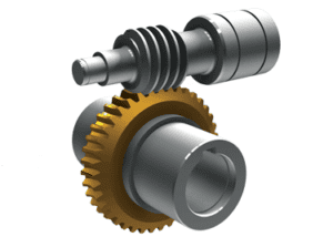
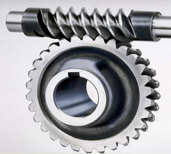
- Gear Configuration: A worm gear consists of a threaded worm and a mating gear, known as the worm wheel or worm gear. The worm has a helical thread that meshes with the teeth of the worm wheel. In contrast, other types of gears, such as spur gears, bevel gears, and helical gears, have parallel or intersecting axes of rotation.
- Gear Ratio: Worm gears provide high gear reduction ratios compared to other types of gears. The ratio is determined by the number of teeth on the worm wheel and the number of threads on the worm. This high reduction ratio allows worm gears to transmit more torque while maintaining a compact size.
- Direction of Rotation: In a worm gear system, the worm can drive the worm wheel, but the reverse is not true. This is due to the self-locking nature of worm gears. The angle of the worm’s helical thread creates a wedging action that prevents the worm wheel from backdriving the worm. This characteristic makes worm gears suitable for applications requiring a mechanical brake or holding position.
- Efficiency: Worm gears typically have lower efficiency compared to other types of gears. This is primarily due to the sliding action between the worm’s threads and the worm wheel’s teeth, which leads to higher friction and energy losses. Therefore, worm gears are not ideal for applications that require high efficiency or continuous, high-speed operation.
- Lubrication: Worm gears require proper lubrication to reduce friction and wear. The sliding action between the worm and the worm wheel generates heat, which can affect the performance and lifespan of the gear system. Lubricants help to dissipate heat and provide a protective film between the mating surfaces, reducing friction and extending the gear’s life.
- Applications: Worm gears are commonly used in applications that require high gear reduction, compact size, and self-locking capabilities. They are found in various industries, including elevators, automotive steering systems, machine tools, robotics, and winding mechanisms.
Overall, the unique design and characteristics of worm gears make them suitable for specific applications where high torque, compactness, and self-locking features are essential, even though they may have lower efficiency compared to other types of gears.


editor by CX 2024-04-04
