Product Description
We are a professional company in bulk material handling, transportation, storage, processing, accessory equipment design, integration and manufacturing. We can provide a complete set of solutions. Thank you for reading the information and welcome to purchase! Welcome to agent distribution!
Brief introduction of the company’s manufacturing capacity
The company’s headquarters, technology and sales are located in Lingang New Area of China (ZheJiang ) pilot free trade zone, The company’s manufacture base is located in Xihu (West Lake) Dis. county, ZHangZhoug Province, which is known as “the most beautiful county in China”. It is 65 kilometers away from HangZhou city and 60 kilometers away from Qiandao Lake. The transportation to Xihu (West Lake) Dis. county from other places is very convenient. No matter by railway, highway or waterway. The manufacture base has a total plant area of around 30000 square CHINAMFG and workshop is equipped with more than 300 sets of various advance manufacture equipment, including 20 sets of CNC precision vertical lathe MODEL: SMVTM12000×50/150, CNC vertical lathe MODEL:DVT8000×30/32, CNC horizontal lathe, MODEL: CK61315×125/32, CNC horizontal lathe MODEL:CK61200×80/32, CNC Grounding boring and milling machine MODEL:TJK6920,etc.Most of the parts are machined by using CNC machine equipment. Theis is a hot treatment CHINAMFG with size 10.5m×8m×8m. The manufacture base also equipped with lifting capacity of 25t, 50t, 100t, 200t overhead crane to handle heavy workpiece and assembly work.
Metalworking equipment
| Name of equipment | Model number | Quantity | SCOPE of application | |
| A | Lathes | |||
| 1 | Vertical Lathe | Numerical control | 1 | Φ 12000 |
| 2 | Vertical Lathe | Numerical control | 1 | Φ 8000 |
| 3 | Vertical Lathe | 1 | Φ 1600 | |
| 4 | Vertical Lathe | C5112A | 1 | Ф 1250 |
| 5 | Horizontal Lathe | Numerical control | 1 | CK61315×12×100T |
| 6 | Horizontal Lathe | CW61200 | 1 | Ф 2000×8000 |
| 7 | Horizontal Lathe | CW61160 | 1 | Ф 1600×6500 |
| 8 | Horizontal Lathe | CW6180 | 2 | Ф 800×3000 |
| 9 | Horizontal Lathe | CW61125 | 2 | Ф 1250×5000 |
| 10 | Horizontal Lathe (remodel) | CW62500 | 2 | Ф 2800×6000 |
| 11 | Common Lathe | CY6140 | 3 | Ф 400×1000 |
| 12 | Common Lathe | CA6140 | 3 | Ф 400×1500 |
| 13 | Common Lathe | C620 | 2 | Ф 400×1400 |
| 14 | Common Lathe | C616 | 1 | Ф 320×1000 |
| 15 | Common Lathe | C650 | 1 | Ф 650×2000 |
| B | Drilling machine | |||
| 1 | Radial drilling machine | Z3080 | 3 | Ф 80×2500 |
| 2 | Radial drilling machine | Z3040 | 2 | Ф 60×1600 |
| 3 | Universal drilling machine | ZW3725 | 3 | Ф 25×880 |
| C | Planing machine | |||
| 1 | Shaper | B665 | 1 | L650 |
| 2 | Hydraulic Shaper | B690 | 1 | L900 |
| 3 | Gantry Planer | HD–16 | 1 | L10000×B1600 |
| D | Milling Machine | |||
| 1 | 4 Coordinate Milling Machine | Numerical control | 1 | 2500×4000 |
| 2 | Gantry milling machine | Numerical contro | 1 | 16mx5mx3m |
| 3 | Gantry milling machine | Numerical contro | 1 | 12mx4mx2.5m |
| 4 | Gantry milling and boring machine | Numerical contro | 1 | Φ 250 |
| 5 | Vertical Milling Machine | XS5054 | 1 | 1600×400 |
| 6 | Horizontal Milling Machine | C62W | 1 | 1250×320 |
| 7 | Horizontal Milling Machine | X60 | 1 | 800×200 |
| 8 | Gantry milling machine | X2014J | 1 | L4000×B1400 |
| 9 | Gantry milling machine | X2571J | 1 | L3000×B1000 |
| 10 | Floor end milling | TX32-1 | 1 | L1500×H800 |
| E | Grinding machine | |||
| 1 | External Grinder | M131W | 1 | Ф 300×1000 |
| 2 | External Grinder | M1432B | 1 | Ф 320×15000 |
| 3 | Surface Grinder | M7130 | 1 | L 1000×300 |
| 4 | Tool grinder | M6571C | 1 | Ф 250 |
| F | Boring machine | |||
| 1 | Floor-standing milling and boring machine | TJK6920 | 1 | X12000 × Y4500 × Z1000 |
| 2 | Boring machine | TSPX619 | 1 | Ф 1000 |
| 3 | Boring machine | T616 | 1 | Ф 800 |
| 4 | Boring machine | T611 | 1 | Ф 800 |
| G | Slotted bed | |||
| 1 | Slotted bed | B5032 | 1 | H320 |
| H | Other machine tools | |||
| 1 | Gear hobbing machine | Y3150 | 1 | Ф 500 M=6 |
| 2 | Hacksaw machine | G7571 | 1 | Ф 220 |
Products and services available
Material handling equipment
Storage equipment
Conveying equipment
Feeding equipment
Component of conveying system
Belt conveyor parts
Large and medium sized finishing parts
If you need above products, please contact us!
ZheJiang Sunshine Industrial Technology Co. , Ltd.
/* January 22, 2571 19:08:37 */!function(){function s(e,r){var a,o={};try{e&&e.split(“,”).forEach(function(e,t){e&&(a=e.match(/(.*?):(.*)$/))&&1
| Application: | Motor, Electric Cars, Motorcycle, Machinery, Marine, Toy, Agricultural Machinery, Car, Customization |
|---|---|
| Hardness: | Customization |
| Gear Position: | Customization |
.shipping-cost-tm .tm-status-off{background: none;padding:0;color: #1470cc}
|
Shipping Cost:
Estimated freight per unit. |
about shipping cost and estimated delivery time. |
|---|
| Payment Method: |
|
|---|---|
|
Initial Payment Full Payment |
| Currency: | US$ |
|---|
| Return&refunds: | You can apply for a refund up to 30 days after receipt of the products. |
|---|

Can worm gears be used in precision manufacturing equipment?
Yes, worm gears can be used in precision manufacturing equipment. Here’s a detailed explanation of their use in precision manufacturing:
1. Precision Motion Control: Worm gears can provide precise motion control in manufacturing equipment. Their design allows for high gear ratios, which enables fine adjustments and precise positioning. This is particularly useful in applications where accurate and repeatable movement is required, such as CNC machines, robotic arms, and coordinate measuring machines (CMMs).
2. Load Holding and Backdriving Prevention: Worm gears have a self-locking characteristic, meaning they can hold loads in position without the need for additional brakes or clutches. This feature is advantageous in precision manufacturing equipment where holding a position is critical. The self-locking property also helps prevent backdriving, ensuring stability and accuracy during operation.
3. Compact Design: Worm gears have a compact design, which can be beneficial in space-constrained manufacturing equipment. Their worm and worm wheel configuration allows for a compact footprint, making them suitable for applications where size limitations exist.
4. High Torque Transmission: Worm gears can transmit high torque, making them suitable for heavy-duty precision manufacturing equipment. The meshing of the worm and worm wheel generates a large contact area, enabling efficient power transfer and load handling capabilities.
5. Reduced Noise and Vibration: Worm gears operate with a sliding motion rather than a rolling motion, resulting in reduced noise and vibration levels. This characteristic is advantageous in precision manufacturing equipment, as it helps maintain a quieter working environment and minimizes potential disturbances that could affect the precision of the manufacturing process.
6. Lubrication and Maintenance: Proper lubrication is crucial for the efficient and reliable operation of worm gears in precision manufacturing equipment. Lubricants help reduce friction and wear between the gear teeth, ensuring smooth and accurate motion. Regular maintenance and lubrication schedules should be followed to optimize gear performance and extend their service life.
While worm gears offer several advantages in precision manufacturing equipment, it’s important to consider the specific requirements of the application. Factors such as gear ratio, efficiency, backlash, and operating conditions should be carefully evaluated to ensure that worm gears are the appropriate choice for achieving the desired precision and performance.
Overall, worm gears can be successfully utilized in precision manufacturing equipment, providing precise motion control, load holding capabilities, compactness, and high torque transmission. When properly selected, installed, and maintained, worm gears can contribute to the accuracy, reliability, and efficiency of precision manufacturing processes.

How do you retrofit an existing mechanical system with a worm gear?
When retrofitting an existing mechanical system with a worm gear, several considerations need to be taken into account. Here’s a detailed explanation of the retrofitting process:
- Evaluate the existing system: Before proceeding with the retrofit, thoroughly assess the existing mechanical system. Understand its design, function, and limitations. Identify the specific reasons for considering a worm gear retrofit, such as the need for increased torque, improved efficiency, or enhanced precision.
- Analyze compatibility: Evaluate the compatibility of a worm gear with the existing system. Consider factors such as available space, structural integrity, alignment requirements, and the load-bearing capacity of the system. Ensure that the addition of a worm gear will not compromise the overall performance or safety of the system.
- Select the appropriate worm gear: Based on the requirements and constraints of the retrofit, choose a suitable worm gear. Consider factors such as gear ratio, torque capacity, efficiency, backlash, and mounting options. Select a worm gear that matches the specific needs of the retrofit and is compatible with the existing system.
- Modify or adapt the system: Depending on the compatibility analysis, it may be necessary to modify or adapt certain components of the existing system to accommodate the worm gear. This can involve making adjustments to shafts, bearings, housings, or other mechanical elements. Ensure that any modifications or adaptations are carried out with precision and adhere to industry standards.
- Install the worm gear: Install the selected worm gear into the modified or adapted system. Follow the manufacturer’s instructions and guidelines for proper installation. Pay attention to torque specifications, lubrication requirements, and any specific assembly procedures. Ensure that the worm gear is securely mounted and aligned to minimize misalignment and maximize performance.
- Test and optimize: After the installation, thoroughly test the retrofitted system to ensure its functionality and performance. Conduct tests to verify torque transmission, efficiency, backlash, noise levels, and any other relevant parameters. Monitor the system during operation and make any necessary adjustments or optimizations to fine-tune its performance.
- Document and maintain: Document the retrofitting process, including any modifications, adjustments, or optimizations made to the existing system. Keep records of installation procedures, test results, and maintenance activities. Regularly inspect and maintain the retrofitted system to ensure its continued performance and reliability.
It’s important to note that retrofitting an existing mechanical system with a worm gear requires expertise in mechanical engineering and an understanding of the specific system requirements. If you lack the necessary knowledge or experience, it is advisable to consult with professionals or engineers specializing in power transmission systems to ensure a successful retrofit.

Can you explain the concept of worm and worm wheel in a worm gear?
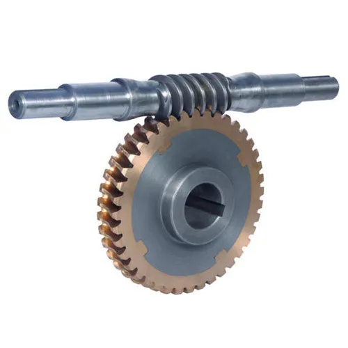
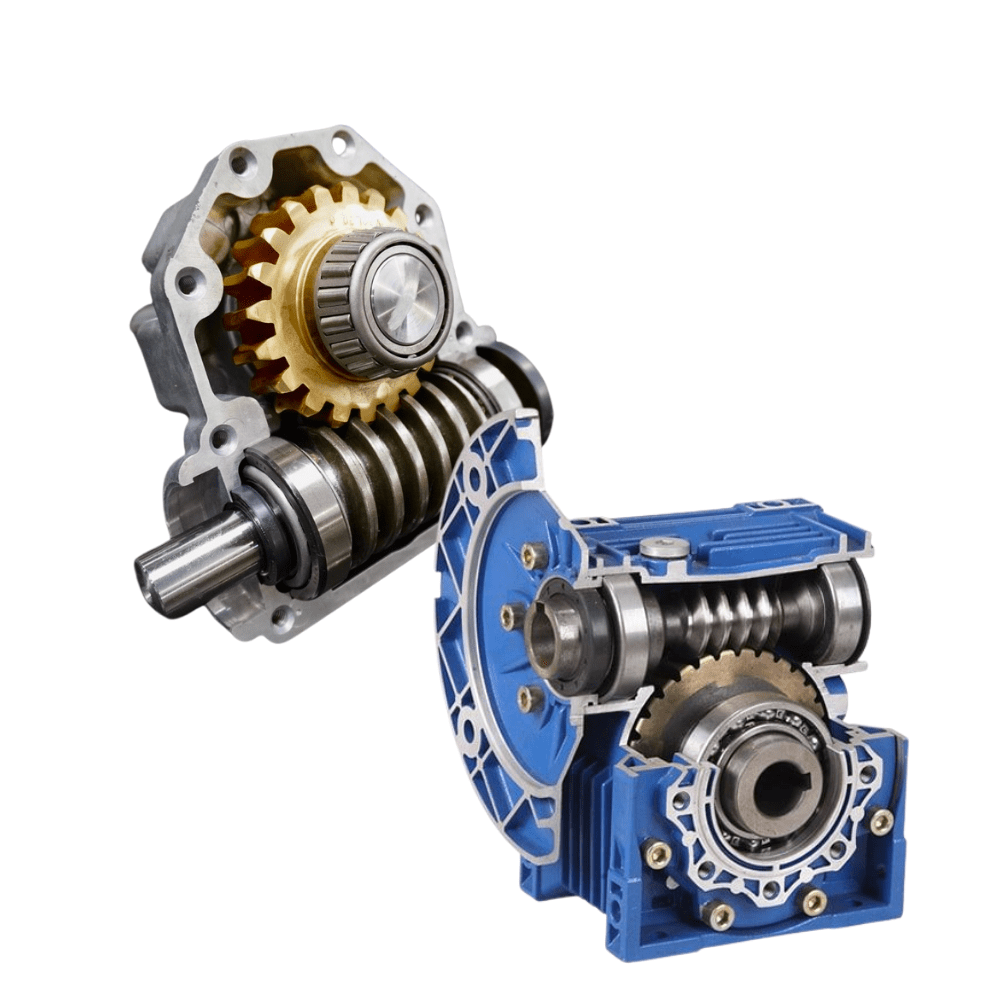
In a worm gear system, the worm and worm wheel are the two primary components that work together to transmit motion and power. Here’s an explanation of the concept:
Worm:
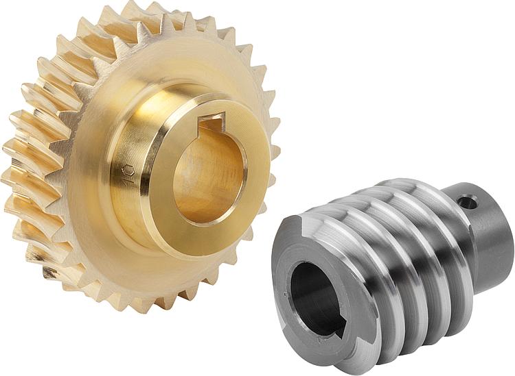
The worm is a cylindrical shaft with a helical thread wrapped around it. It resembles a screw with a spiral groove. The helical thread is called the worm’s thread or worm thread. The worm is the driving component in the worm gear system.
When the worm rotates, the helical thread engages with the teeth of the worm wheel, causing the worm wheel to rotate. The angle of the helical thread creates a wedging action against the teeth of the worm wheel, resulting in a high gear reduction ratio.
One important characteristic of the worm is its self-locking nature. Due to the angle of the helical thread, the worm can drive the worm wheel, but the reverse is not true. The self-locking feature prevents the worm wheel from backdriving the worm, providing a mechanical brake or holding position in the system.
The worm can be made from various materials such as steel, bronze, or even plastics, depending on the application requirements. It is often mounted on a shaft and supported by bearings for smooth rotation.
Worm Wheel:
The worm wheel, also known as the worm gear, is the driven component in the worm gear system. It is a gear with teeth that mesh with the helical thread of the worm. The teeth on the worm wheel are typically helical and cut to match the angle and pitch of the worm’s thread.
As the worm rotates, its helical thread engages with the teeth of the worm wheel, causing the worm wheel to rotate. The rotation of the worm wheel is in the same direction as the worm’s rotation, but the speed is significantly reduced due to the high gear reduction ratio of the worm gear system.
The worm wheel is usually larger in diameter compared to the worm, allowing for a higher gear reduction ratio. It can be made from materials such as steel, bronze, or cast iron, depending on the application’s torque and durability requirements.
Together, the worm and worm wheel form a compact and efficient gear system that provides high gear reduction and self-locking capabilities. They are commonly used in various applications where precise motion control, high torque, and compactness are required, such as elevators, steering systems, and machine tools.


editor by CX 2024-03-27
