Product Description
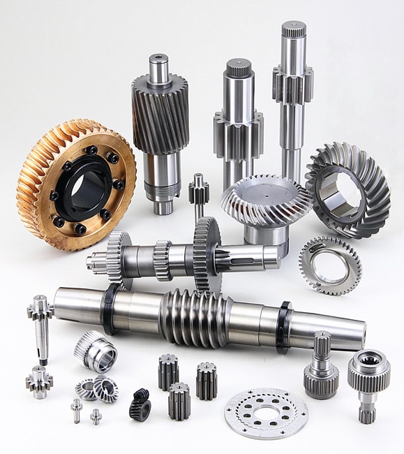
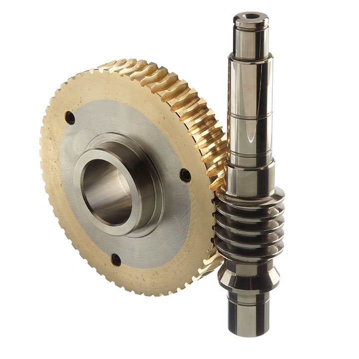
High quality plastic Oil Nylon MC901 PA rack worm gear
Description:
Nylon PA6 Sheets & Rods that made the with 100% Virgin Raw Material by HangZhou Engineering Plastics Industries (Group) Company, has the best performance, such as: very tough, even at low temperatures, and high hardness in the surface, toughness, mechanical lower shock, and abrasion resistance. Combined with these characteristics and good insulation, and chemical properties, it has become common-level materials.
Its widely used in a variety of mechanical structures and spare parts. Nylon PA6 products that made by HangZhou Engineering Plastics Industries (Group) Company, has the higher hardness, rigidity, a good resistance to wear and heat deflection temperature.
Advantages:
1. Good Tensile strength;
2. High impact and notching impact strength;
3. High heat deflection temperature ;
4. High strength and stiffness;
5. Good glide and limp home characters;
6. Good chemical stability against organic solvents and fuels;
7. Resistant to thermal aging (applicable temperature between -50°C and 110°C;
8. Size alternation by humidity absorption must be considered;
Application:
1. Nylon PA6 Products that made by HangZhou Engineering Plastics Industries (Group) Company is widely substituted for wear parts of mechanical equipment, or used as quick-wear parts of equipment instead of copper and alloy;
2. Shaft sleeve, bearing bush, lining, lining plate, gear;
3. Worm gear, roller copper guide rail, piston ring, seal ring, slide block;
4. Spheric bowl, impeller, blade, cam, nut, valve plate,
5. Pipe, stuffing box, rack, belt pulley, pump rotor, etc.
Main Properties of Nylon
| Property | Item No. | Unit | MC Nylon (Natural) | Oil Nylon+Carbon (Black) | Oil Nylon (Green) | MC901 (Blue) | MC Nylon+MSO2 (Light black) | |
| Mechanical Properties | 1 | Density | g/cm3 | 1.15 | 1.15 | 1.135 | 1.15 | 1.16 |
| 2 | Water absorption (23ºC in air) | % | 1.8-2.0 | 1.8-2.0 | 2 | 2.3 | 2.4 | |
| 3 | Tensile strength | MPa | 89 | 75.3 | 70 | 81 | 78 | |
| 4 | Tensile strain at break | % | 29 | 22.7 | 25 | 35 | 25 | |
| 5 | Compressive stress(at 2%nominal strain) | MPa | 51 | 51 | 43 | 47 | 49 | |
| 6 | Charpy impact strength (unnotched) | KJ/m2 | No break | No break | ≥50 | No BK | No break | |
| 7 | Charpy impact strength (notched) | KJ/m2 | ≥5.7 | ≥6.4 | 4 | 3.5 | 3.5 | |
| 8 | Tensile modulus of elasticity | MPa | 3190 | 3130 | 3000 | 3200 | 3300 | |
| 9 | Ball indentation hardness | N/mm2 | 164 | 150 | 145 | 160 | 160 | |
| 10 | Rockwell hardness | – | M88 | M87 | M82 | M85 | M84 | |
| Application: | Motor, Electric Cars, Motorcycle, Machinery, Marine, Toy, Agricultural Machinery, Car, Domestic Appliances |
|---|---|
| Hardness: | Hardened Tooth Surface |
| Gear Position: | External Gear |
| Manufacturing Method: | Cut Gear |
| Toothed Portion Shape: | Bevel Wheel |
| Material: | Nylon |
| Customization: |
Available
| Customized Request |
|---|

What lubrication is required for a worm gear?
The lubrication requirements for a worm gear system are crucial to ensure smooth operation, reduce friction, prevent wear, and extend the lifespan of the gears. The specific lubrication needed may vary depending on factors such as the application, operating conditions, gear materials, and manufacturer recommendations. Here are some key considerations regarding lubrication for a worm gear:
- Lubricant selection: Choose a lubricant specifically designed for gear applications, taking into account factors such as load, speed, temperature, and environment. Common lubricant types for worm gears include mineral oils, synthetic oils, and greases. Consult the gear manufacturer’s recommendations or industry standards to determine the appropriate lubricant type and viscosity grade.
- Viscosity: The lubricant viscosity is critical for effective lubrication. The viscosity should be selected based on the operating conditions and gear design parameters. Higher loads and slower speeds typically require higher viscosity lubricants to ensure sufficient film thickness and protection. Conversely, lower viscosity lubricants may be suitable for lighter loads and higher speeds to minimize power losses.
- Lubrication method: The lubrication method can vary depending on the gear system design. Some worm gears have oil sumps or reservoirs that allow for oil bath lubrication, where the gears are partially submerged in a lubricant pool. Other systems may require periodic oil application or greasing. Follow the gear manufacturer’s guidelines for the appropriate lubrication method, frequency, and quantity.
- Temperature considerations: Worm gear systems may encounter a wide range of temperatures during operation. Ensure that the selected lubricant can withstand the anticipated temperature extremes without significant degradation or viscosity changes. Extreme temperatures may require specialized high-temperature or low-temperature lubricants to maintain proper lubrication performance.
- Maintenance and monitoring: Regular maintenance and monitoring of the lubrication are essential for optimal gear performance. Periodically inspect the lubricant condition, including its cleanliness, viscosity, and contamination levels. Monitor operating temperatures and perform oil analysis if necessary. Replace the lubricant at recommended intervals or if signs of degradation or contamination are observed.
It’s important to note that the lubrication requirements may vary for different worm gear applications, such as automotive, industrial machinery, or marine systems. Additionally, environmental factors such as dust, moisture, or chemical exposure should be considered when selecting a lubricant and establishing a lubrication maintenance plan.
Always refer to the gear manufacturer’s recommendations and guidelines for the specific lubrication requirements of your worm gear system. Adhering to proper lubrication practices helps ensure smooth and reliable operation, minimizes wear, and maximizes the gear system’s longevity.

What are the potential challenges in designing and manufacturing worm gears?
Designing and manufacturing worm gears can present several challenges due to their unique characteristics and operating conditions. Here’s a detailed explanation of the potential challenges involved:
- Complex geometry: Worm gears have complex geometry with helical threads on the worm shaft and corresponding teeth on the worm wheel. Designing the precise geometry of the gear teeth, including the helix angle, lead angle, and tooth profile, requires careful analysis and calculation to ensure proper meshing and efficient power transmission.
- Gear materials and heat treatment: Selecting suitable materials for worm gears is critical to ensure strength, wear resistance, and durability. The materials must have good friction and wear properties, as well as the ability to withstand the sliding and rolling contact between the worm and the worm wheel. Additionally, heat treatment processes such as carburizing or induction hardening may be necessary to enhance the gear’s surface hardness and improve its load-carrying capacity.
- Lubrication and cooling: Worm gears operate under high contact pressures and sliding velocities, resulting in significant heat generation and lubrication challenges. Proper lubrication is crucial to reduce friction, wear, and heat buildup. Ensuring effective lubricant distribution to all contact surfaces, managing lubricant temperature, and providing adequate cooling mechanisms are important considerations in worm gear design and manufacturing.
- Backlash control: Controlling backlash, which is the clearance between the worm and the worm wheel, is crucial for precise motion control and positional accuracy. Designing the gear teeth and adjusting the clearances to minimize backlash while maintaining proper tooth engagement is a challenge that requires careful consideration of factors such as gear geometry, tolerances, and manufacturing processes.
- Manufacturing accuracy: Achieving the required manufacturing accuracy in worm gears can be challenging due to their complex geometry and tight tolerances. The accurate machining of gear teeth, maintaining proper tooth profiles, and achieving the desired surface finish require advanced machining techniques, specialized tools, and skilled operators.
- Noise and vibration: Worm gears can generate noise and vibration due to the sliding contact between the gear teeth. Designing the gear geometry, tooth profiles, and surface finishes to minimize noise and vibration is a challenge. Additionally, the selection of appropriate materials, lubrication methods, and gear housing design can help reduce noise and vibration levels.
- Efficiency and power loss: Worm gears inherently have lower efficiency compared to other types of gear systems due to the sliding contact and high gear ratios. Minimizing power loss and improving efficiency through optimized gear design, material selection, lubrication, and manufacturing accuracy is a challenge that requires careful balancing of various factors.
- Wear and fatigue: Worm gears are subjected to high contact stresses and cyclic loading, which can lead to wear, pitting, and fatigue failure. Designing the gear teeth for proper load distribution, selecting appropriate materials, and applying suitable surface treatments or coatings are essential to mitigate wear and fatigue issues.
- Cost considerations: Designing and manufacturing worm gears can be cost-intensive due to the complexity of the gear geometry, material requirements, and precision manufacturing processes. Balancing performance requirements with cost considerations is a challenge that requires careful evaluation of the gear’s intended application, performance expectations, and budget constraints.
Addressing these challenges requires a comprehensive understanding of gear design principles, manufacturing processes, material science, and lubrication technologies. Collaboration between design engineers, manufacturing experts, and material specialists is often necessary to overcome these challenges and ensure the successful design and production of high-quality worm gears.

How do you calculate the gear ratio of a worm gear?
Calculating the gear ratio of a worm gear involves determining the number of teeth on the worm wheel and the pitch diameter of both the worm and worm wheel. Here’s the step-by-step process:
- Determine the number of teeth on the worm wheel (Zworm wheel). This information can usually be obtained from the gear specifications or by physically counting the teeth.
- Measure or determine the pitch diameter of the worm (Dworm) and the worm wheel (Dworm wheel). The pitch diameter is the diameter of the reference circle that corresponds to the pitch of the gear. It can be measured directly or calculated using the formula: Dpitch = (Z / P), where Z is the number of teeth and P is the circular pitch (the distance between corresponding points on adjacent teeth).
- Calculate the gear ratio (GR) using the following formula: GR = (Zworm wheel / Zworm) * (Dworm wheel / Dworm).
The gear ratio represents the speed reduction and torque multiplication provided by the worm gear system. A higher gear ratio indicates a greater reduction in speed and higher torque output, while a lower gear ratio results in less speed reduction and lower torque output.
It’s worth noting that in worm gear systems, the gear ratio is also influenced by the helix angle and lead angle of the worm. These angles determine the rate of rotation and axial movement per revolution of the worm. Therefore, when selecting a worm gear, it’s important to consider not only the gear ratio but also the specific design parameters and performance characteristics of the worm and worm wheel.


editor by CX 2023-11-08
