Product Description
| Product Model | SWL2.5, SWL5, SWL10, SWL15, SWL20, SWL25, SWL35, SWL50, SWL100, SWL120 |
| Product Description | Basic lifting component, compact structure, small size, light weight, no noise, safe and convenient, flexible use, high reliability, wide power source, multiple supporting functions, long service life |
| Usage | Single or combined use, can accurately control the adjustment of lifting or pushing height according to a certain program, can be directly driven by motor or other power, can also be manual |
| Lifting Efficiency and Load Capacity | Special and advanced technology has been developed to improve the overall performance of the jack |
| Structural Type | Type 1 – Screw moves axially; Type 2 – Screw rotates, nut moves axially |
| Assembly Type | Type A – Screw/nut moves upwards; Type B – Screw/nut moves downwards |
| Screw Head Type | Type 1 structure screw head: Type I (cylindrical), Type II (flange), Type III (threaded), Type IV (flat head); Type 2 structure screw head: Type I (cylindrical), Type III (threaded) |
| Transmission Ratio | Ordinary speed ratio (P), slow speed ratio (M), medium speed ratio (F) can be customized according to user requirements |
| Lifting Load Capacity | 2.5kN, 5kN, 10kN, 15kN, 20kN, 25kN, 35kN, 50kN, 100kN, 120kN |
| Screw Protection | Type 1 structure: basic type (no protection), anti-rotation type (F), with protective cover (Z), anti-rotation and protective cover (FZ); Type 2 structure: basic type (no protection) |
Product description: SWL series worm gear screw lift is a basic lifting component with many advantages such as compact structure, small volume, light weight, no noise, safety and convenience, flexible use, high reliability, wide power source, many supporting functions and long service life. It can be used singly or in combination, can adjust the height of lifting or advancing accurately according to certain procedures, and can be driven directly by electric motor or other power, or manually. In order to improve the efficiency and carrying capacity of SWL series worm gear screw lift, special and advanced technology is developed to improve the comprehensive performance of the lift to meet the requirements of the majority of customers. SWL series worm gear screw lift has different structure types and assembly types, and the lifting height can be customized according to the user’s requirements.
RFQ
Q:What information should I tell you to confirm speed reducer?
A: Model/Size, Transmission Ratio, Shaft directions & Order quantity.
Q:What if I don’t know which gear reducer I need?
A:Don’t worry, Send as much information as you can, our team will help you find the right 1 you are looking for.
Q:What should I provide if I want to order NON-STANDERD speed reducers?
A: Drafts, Dimensions, Pictures and samples if possible.
Q:What is the MOQ?
A: It is OK for 1 or small pieces trial order for quality testing.
Q:How long should I wait for the feedback after I send the inquiry?
A: Within 6 hours
Q:What is the payment term?
A:You can pay via T/T(30% in advance+70% before delivery), L/C ,West Union etc
| Standard or Nonstandard: | Nonstandard |
|---|---|
| Application: | Electric Cars, Motorcycle, Marine, Agricultural Machinery, Car |
| Spiral Line: | Right-Handed Rotation |
| Head: | Single Head |
| Reference Surface: | Toroidal Surface |
| Type: | ZK Worm |
| Samples: |
US$ 100/Piece
1 Piece(Min.Order) | |
|---|

How does a worm gear impact the overall efficiency of a system?
A worm gear has a significant impact on the overall efficiency of a system due to its unique design and mechanical characteristics. Here’s a detailed explanation of how a worm gear affects system efficiency:
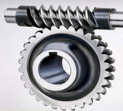
A worm gear consists of a worm (a screw-like gear) and a worm wheel (a cylindrical gear with teeth). When the worm rotates, it engages with the teeth of the worm wheel, causing the wheel to rotate. The main factors influencing the efficiency of a worm gear system are:
- Gear Reduction Ratio: Worm gears are known for their high gear reduction ratios, which are the ratio of the number of teeth on the worm wheel to the number of threads on the worm. This high reduction ratio allows for significant speed reduction and torque multiplication. However, the larger the reduction ratio, the more frictional losses occur, resulting in lower efficiency.
- Mechanical Efficiency: The mechanical efficiency of a worm gear system refers to the ratio of the output power to the input power, accounting for losses due to friction and inefficiencies in power transmission. Worm gears typically have lower mechanical efficiency compared to other gear types, primarily due to the sliding action between the worm and the worm wheel teeth. This sliding contact generates higher frictional losses, resulting in reduced efficiency.
- Self-Locking: One advantageous characteristic of worm gears is their self-locking property. Due to the angle of the worm thread, the worm gear system can prevent the reverse rotation of the output shaft without the need for additional braking mechanisms. While self-locking is beneficial for maintaining position and preventing backdriving, it also increases the frictional losses and reduces the efficiency when the gear system needs to be driven in the opposite direction.
- Lubrication: Proper lubrication is crucial for minimizing friction and maintaining efficient operation of a worm gear system. Inadequate or improper lubrication can lead to increased friction and wear, resulting in lower efficiency. Regular lubrication maintenance, including monitoring viscosity, cleanliness, and lubricant condition, is essential for optimizing efficiency and reducing power losses.
- Design and Manufacturing Quality: The design and manufacturing quality of the worm gear components play a significant role in determining the system’s efficiency. Precise machining, accurate tooth profiles, proper gear meshing, and appropriate surface finishes contribute to reducing friction and enhancing efficiency. High-quality materials with suitable hardness and smoothness also impact the overall efficiency of the system.
- Operating Conditions: The operating conditions, such as the load applied, rotational speed, and temperature, can affect the efficiency of a worm gear system. Higher loads, faster speeds, and extreme temperatures can increase frictional losses and reduce overall efficiency. Proper selection of the worm gear system based on the expected operating conditions is critical for optimizing efficiency.
It’s important to note that while worm gears may have lower mechanical efficiency compared to some other gear types, they offer unique advantages such as high gear reduction ratios, compact design, and self-locking capabilities. The suitability of a worm gear system depends on the specific application requirements and the trade-offs between efficiency, torque transmission, and other factors.
When designing or selecting a worm gear system, it is essential to consider the desired balance between efficiency, torque requirements, positional stability, and other performance factors to ensure optimal overall system efficiency.

What are the potential challenges in designing and manufacturing worm gears?
Designing and manufacturing worm gears can present several challenges due to their unique characteristics and operating conditions. Here’s a detailed explanation of the potential challenges involved:
- Complex geometry: Worm gears have complex geometry with helical threads on the worm shaft and corresponding teeth on the worm wheel. Designing the precise geometry of the gear teeth, including the helix angle, lead angle, and tooth profile, requires careful analysis and calculation to ensure proper meshing and efficient power transmission.
- Gear materials and heat treatment: Selecting suitable materials for worm gears is critical to ensure strength, wear resistance, and durability. The materials must have good friction and wear properties, as well as the ability to withstand the sliding and rolling contact between the worm and the worm wheel. Additionally, heat treatment processes such as carburizing or induction hardening may be necessary to enhance the gear’s surface hardness and improve its load-carrying capacity.
- Lubrication and cooling: Worm gears operate under high contact pressures and sliding velocities, resulting in significant heat generation and lubrication challenges. Proper lubrication is crucial to reduce friction, wear, and heat buildup. Ensuring effective lubricant distribution to all contact surfaces, managing lubricant temperature, and providing adequate cooling mechanisms are important considerations in worm gear design and manufacturing.
- Backlash control: Controlling backlash, which is the clearance between the worm and the worm wheel, is crucial for precise motion control and positional accuracy. Designing the gear teeth and adjusting the clearances to minimize backlash while maintaining proper tooth engagement is a challenge that requires careful consideration of factors such as gear geometry, tolerances, and manufacturing processes.
- Manufacturing accuracy: Achieving the required manufacturing accuracy in worm gears can be challenging due to their complex geometry and tight tolerances. The accurate machining of gear teeth, maintaining proper tooth profiles, and achieving the desired surface finish require advanced machining techniques, specialized tools, and skilled operators.
- Noise and vibration: Worm gears can generate noise and vibration due to the sliding contact between the gear teeth. Designing the gear geometry, tooth profiles, and surface finishes to minimize noise and vibration is a challenge. Additionally, the selection of appropriate materials, lubrication methods, and gear housing design can help reduce noise and vibration levels.
- Efficiency and power loss: Worm gears inherently have lower efficiency compared to other types of gear systems due to the sliding contact and high gear ratios. Minimizing power loss and improving efficiency through optimized gear design, material selection, lubrication, and manufacturing accuracy is a challenge that requires careful balancing of various factors.
- Wear and fatigue: Worm gears are subjected to high contact stresses and cyclic loading, which can lead to wear, pitting, and fatigue failure. Designing the gear teeth for proper load distribution, selecting appropriate materials, and applying suitable surface treatments or coatings are essential to mitigate wear and fatigue issues.
- Cost considerations: Designing and manufacturing worm gears can be cost-intensive due to the complexity of the gear geometry, material requirements, and precision manufacturing processes. Balancing performance requirements with cost considerations is a challenge that requires careful evaluation of the gear’s intended application, performance expectations, and budget constraints.
Addressing these challenges requires a comprehensive understanding of gear design principles, manufacturing processes, material science, and lubrication technologies. Collaboration between design engineers, manufacturing experts, and material specialists is often necessary to overcome these challenges and ensure the successful design and production of high-quality worm gears.

How do you install a worm gear system?
Installing a worm gear system requires careful attention to ensure proper alignment, lubrication, and secure mounting. Here are the general steps involved in installing a worm gear system:
- Prepare the components: Before installation, ensure that all the components of the worm gear system, including the worm, worm wheel, bearings, and housing, are clean and free from any contaminants or damage. Inspect the components for any signs of wear or defects.
- Check alignment: Verify that the mating surfaces of the worm and worm wheel are clean and free from any debris. Ensure that the gear teeth mesh properly and that there is no excessive backlash or misalignment. Make any necessary adjustments or repairs before proceeding with the installation.
- Apply lubrication: Lubricate the worm gear system according to the manufacturer’s recommendations. Select a suitable lubricant that provides sufficient lubrication and reduces friction between the worm and worm wheel during operation. Apply the lubricant evenly to the gear teeth and other contact surfaces.
- Mounting: Position the worm gear system in the desired location, taking into account any space constraints or mounting requirements. Use appropriate fasteners, such as bolts or screws, to securely attach the system to the surrounding structure or base. Ensure that the mounting surfaces are clean, flat, and able to withstand the forces and loads exerted by the gear system.
- Alignment and adjustment: Once the worm gear system is mounted, check the alignment again and make any necessary adjustments. Ensure that the worm and worm wheel are properly engaged and that there is no excessive play or binding. Pay attention to any specified alignment tolerances provided by the manufacturer.
- Testing and operation: After installation, conduct a thorough functional test of the worm gear system. Verify that it operates smoothly, without unusual noise or vibration. Check for proper engagement of the gear teeth and ensure that the system performs as intended under different load conditions. Monitor the system’s performance during initial operation and address any issues or abnormalities promptly.
It’s important to follow the specific installation instructions provided by the gear system manufacturer. Different worm gear designs and applications may have additional installation requirements or considerations that should be taken into account.
Proper installation of a worm gear system ensures its reliable operation, minimizes wear, and maximizes its lifespan. If you are unsure about any aspect of the installation process, it is recommended to consult the manufacturer or seek the assistance of a qualified professional.


editor by CX 2023-11-16
