
fluid coupling
functions
eleven sizes Styles obtainable utilizing couplings (Para-Flex and DGF Gear) or V-Belt drives
Accommodates up to 4.seventy five inch shafts and  1400 horsepower purposes
Smooth, managed acceleration with customizable startup torques
Motor starts off beneath no load, permitting the use of standard NEMA style B motors and potentially reducing motor horsepower necessity
No bodily link is existing, making it possible for for safety below overload situations
Common Industries
Air Managing
Mining
Paper & Forest
typical apps
Conveyors (Bulk Material Handling)
Any software demanding overload defense
Any application with a high-inertia startup
Overview
Fluid coupling on Transfluid’s industrial transmission design KPTO.
A fluid coupling consists of three elements, in addition the hydraulic fluid:
The housing, also known as the shell[5] (which should have an oil-tight seal about the generate shafts), consists of the fluid and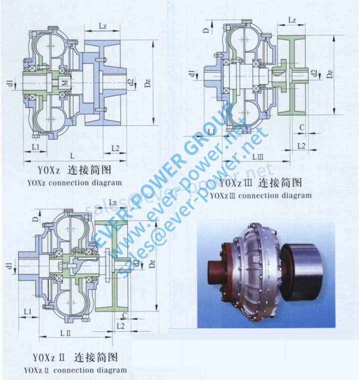 turbines.
Two turbines (fanlike parts):
One particular related to the input shaft recognized as the pump or impeller,[five] primary wheel[five] input turbine
The other linked to the output shaft, known as the turbine, output turbine, secondary wheel[5] or runner
The driving turbine, identified as the ‘pump’, (or driving torus[a]) is rotated by the key mover, which is normally an internal combustion engine or electric motor. The impeller’s motion imparts both outwards linear and rotational movement to the fluid.